반응형
1. UART 비동기 통신 이란
● UART(Universal Asynchronous Receiver and Transmitter)란 비동기 전이중 1:1통신 방식이다.
● 동기통신 PS/2와는 다른 점은 비동기 통신은 최대 입력 전압이 ±15V, 최대 출력 전압이 ±25V로 비교적 높은 전압이다. 그래서 동기통신보다 통신거리가 길고, 최대 통신거리는 15m이다.
● 통신속도는 Baud-rate(bau-rate)라 하고, 가변적인 특성을 갖는다.
● UART는 default시 1의 값을 갖으며, START bit(1 bit),Data(8 bit), PARITY(1 bit), STOP(1 bit) 총 11비트로 전송되고, DATA는 최대 8비트가 기본 단위이다.
● RS-232(가장 많이 쓰임) Tranceiver을 사용하여 TTL(5V) ↔ UART(12V) level로 변환해준다.
● 9600bps ~ 921600bps의 속도에서 일반적으로 9600bps,15200bps를 많이 사용하고, 이번 실습에서는 115200bps를 사용한다
● 115200bps 한 펄스의 주기는 868055us
2. UART_TX (Transmitter) VHDL 코드 & 분석 (library 생략)
entity UART_TX is
port(
nRst : in std_logic;
clk : in std_logic;
start_sig : in std_logic;
data : in std_logic_vector(7 downto 0);
tx : out std_logic;
busy : out std_logic
);
end UART_TX;
architecture beh of UART_TX is
type state_type is (IDLE, START, SEND, PARITY, STOP);
signal state : state_type;
signal cnt : std_logic_vector(8 downto 0);
signal pclk : std_logic;
signal start_d : std_logic;
signal flag : std_logic;
signal temp_data : std_logic_vector(7 downto 0);
signal tx_data : std_logic_vector(7 downto 0);
signal bit_cnt : std_logic_vector(3 downto 0);
begin
process(nRst,clk)
begin
if(nRst = '0') then
start_d <= '0';
flag <= '0';
temp_data <= (others => '0');
elsif rising_edge(clk) then
start_d <= start_sig;
if (start_d = '0') and (start_sig = '1') then
flag <= '1';
temp_data <= data;
elsif (state = START) then
flag <= '0';
end if;
end if;
end process;
process(nRst,clk)
begin
if(nRst = '0') then
cnt <= (others => '0');
pclk <= '0';
elsif rising_edge(clk) then
if(cnt = 433) then
cnt <= (others => '0');
pclk <= not pclk;
else
cnt <= cnt + 1;
end if;
end if;
end process;
process(nRst,pclk)
begin
if(nRst = '0') then
state <= IDLE;
bit_cnt <= (others =>'0');
tx_data <= (others =>'0') ;
busy <= '1';
elsif rising_edge(pclk) then
case state is
when IDLE =>
if(flag = '1') then
state <= START;
else
state <= IDLE;
end if;
bit_cnt <= (others =>'0');
tx_data <= (others =>'0');
busy <= '1';
when START =>
state <= SEND;
tx_data <= temp_data;
busy <= '0';
when SEND =>
if(bit_cnt = 7) then
bit_cnt <= (others =>'0');
state <= PARITY;
else
bit_cnt <= bit_cnt + 1;
tx_data <= '0' & tx_data(7 downto 1);
end if;
when PARITY =>
state <= STOP;
when STOP =>
state <= IDLE;
busy <= '1';
when others =>
end case;
end if;
end process;
tx <= tx_data(0) when state = SEND else
'0' when state = START or state = PARITY else
'1';
end beh;
3.UART_TX 결과 및 시뮬레이션
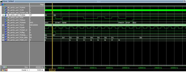
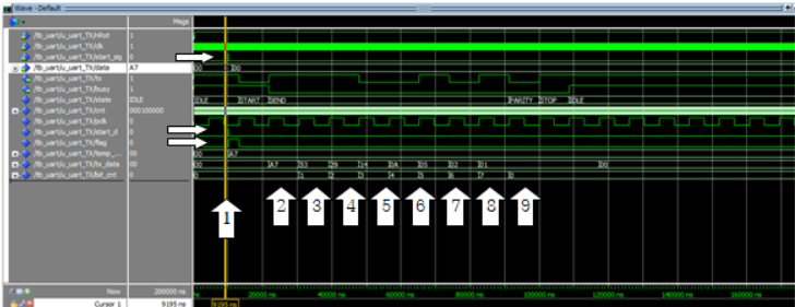
(1) data값에 A7이 입력되면서 start_sig값과 이값으로부터 전달 받은 start_d에 의해 시작신호가 형성되면서 flag값에 1의 값이 나오면서 START상태로 넘어간다.
START상태에선 tx_data값에 data값이 전달되어 임시저장된 temp_data의 값을 전달해주고 SEND상태로 넘어가면서 busy값에 0을 전달해준다
(2) SNEND상태에서 입력받은 A7(1010 0111)의 0비트 값 1이 tx로 전달되고 다음에 bit_cnt(비트카운트)의 수는 1이된다.
tx_data값에 0비트가 tx로 전달되어 비어있으므로 8비트에 0을 채워놓고 기존 tx_data의 7~1비트의 수를 6~0비트로 우측 씩 shfit하여 이 값을 tx_data로 전달 해준다.
(3) ~ (8) bit_cnt, 즉 비트수가 7이 될 때 까지, (2)번의 과정을 전달하여 우측부터 A7(1010 0111)의 우측부터 좌측으로 차례차례 tx로 전달하여 준다.
(9) bit_cnt의 값이 7 (8비트전달) 이 되었을 때, bit_cnt의 값을 0으로 초기화 해주고 다음 상태인 PARITY상태로 넘어가고 STOP으로 넘어가 초기상태인 IDLE상태로 만들어준다.
2. UART_RX (RECEIVER) VHDL 코드 & 분석 (library 생략)
entity UART_RX is
port(
nRst : in std_logic;
clk : in std_logic;
serialin : in std_logic;
rx_data : out std_logic_vector(7 downto 0);
valid : out std_logic
);
end UART_RX;
architecture beh of UART_RX is
type state_type is ( IDLE, START, RECEIVE, PARITY, STOP);
signal state : state_type;
signal cnt : std_logic_vector(5 downto 0);
signal pclk : std_logic;
signal pcnt : std_logic_vector(2 downto 0);
signal bit_cnt : std_logic_vector (2 downto 0);
signal serialin_d : std_logic;
signal flag : std_logic;
signal xmtdata : std_logic_vector(7 downto 0);
begin
process(nRst,clk)
begin
if(nRst = '0') then
cnt <= (others =>'0');
pclk<='0';
elsif rising_edge(clk) then
if(cnt=53) then
cnt<=(others => '0');
pclk<=not pclk;
else
cnt<=cnt+1;
end if;
end if;
end process;
process(nRst,clk)
begin
if(nRst='0') then
serialin_d<='0';
flag<='0';
elsif rising_edge(clk) then
serialin_d <= serialin;
if state = IDLE then
if(serialin_d = '1') and (serialin='0') then
flag <= '1';
end if;
elsif state = START then
flag <= '0' ;
end if;
end if;
end process;
process(nRst,pclk)
begin
if(nRst = '0') then
state <= IDLE;
pcnt<= (others => '0');
bit_cnt<= (others => '0');
xmtdata<= (others => '0');
rx_data<= (others => '0');
elsif rising_edge(pclk) then
case state is
when IDLE=>
if(flag='1') then
state <= START;
else
state <= IDLE;
end if;
pcnt<= (others => '0');
bit_cnt<= (others => '0');
xmtdata<= (others => '0');
rx_data <= (others => '0');
when START =>
if(pcnt = 3 ) then
pcnt <= (others => '0');
state <= RECEIVE;
else
pcnt <= pcnt + 1;
state <= START ;
end if;
when RECEIVE =>
if(pcnt = 7) then
pcnt <=(others =>'0');
xmtdata <= serialin&xmtdata(7 downto 1);
if(bit_cnt = 7 ) then
bit_cnt <= (others => '0');
state <=PARITY;
else
bit_cnt <= bit_cnt + 1;
state <= RECEIVE;
end if;
else
pcnt <= pcnt + 1;
end if;
when PARITY =>
if(pcnt=7) then
pcnt<=(others =>'0');
state <= STOP;
else
pcnt<=pcnt+1;
state<=PARITY;
end if;
when STOP =>
if(pcnt=7) then
pcnt <= (others => '0');
state <= IDLE;
else
pcnt <= pcnt + 1;
state <= STOP;
end if;
rx_data<=xmtdata;
when others =>
state<=IDLE;
end case;
end if;
end process;
valid <= '1' when (state = STOP and pcnt=7)else '0';
end beh;
3.UART_RX 결과 및 시뮬레이션


(1) serialin과 serialin_d에 의해 flag값이 1로 결정되고 상태가 START로 넘어간다.
(2) START상태에서 flag값을 다시 0으로 만들어주고 RECEIVE로 넘어간다
(3) RECEIVE상태에서 serialin에서 1이 들어 왔는데 바로 xmtdata에 전달이 안되고, pcnt의 7의값(들어온 data의 중간시기)를 읽으므로 (2)번에서 serialin의 1의 값이 (3)번 시점 에서 읽힌다, 처음1이 들어와 1 & xmtdata(7 downto 0)가 되고, xmtdata는 0000 0000이므로 1000 0000 (16진수로 80)이 xmtdata로 전달됨, 1개를 전달받았으니 bit_cnt의 수는 0이다.
(4) bit_cnt의 수는7이 아니므로 RECEIVE상태에서 데이터 8비트를 다 안받은상태이다. serialin에서 1이 또 들어왔기 때문에 xmtdata에 1 & xmtdata(7 downto 1) => 1 & 100 0000 이 되므로 1100 0000(16진수로 C0)가 xmtdata에 전달된다. 그리고 bit_cnt의 수는 1이 된다 (비트수2개)
(5) ~ (9) 3,4번의 과정을 bit_cnt의 수가 7,즉 비트수가 8개가 될 때 까지 반복한다.
(10) PARITY상태에서 STOP상태로 넘어가고,
STOP상태에서 최종 xmtdata값은 A7(16진수)가 되고 이값은 rx_data값으로 전달된다. 이 후 다시 모든 값을 0으로 초기화하고 기본상태인 IDLE상태로 된다.
반응형
'일상 > SOC' 카테고리의 다른 글
| DE2 보드 UART_RX 동작 내용,UART_TX 동작 내용 (0) | 2021.06.10 |
|---|---|
| simple_U_processor VHDL/TESTBENCH (0) | 2021.06.10 |
| ps/2 keyboard DE2보드 동작/ps2통신 키보드 DE2 내용 및분석 (0) | 2021.06.10 |
| ps/2 keyboard testbench, ps/2키보드테스트벤치 parsing vhdl (0) | 2021.06.10 |
| Ps/2통신 - 키보드 receiver,ps/2 keyboard receiver VHDL,SOC,MODELSIM (0) | 2021.06.09 |


